The noise produced by machinery or equipment is a technical characteristic generally expressed in terms of acoustic power (power level in dB relative to a reference acoustic power of 10-12 watts). When this project was started, the experimental determination of power was based on acoustic pressure measurements taken using microphones. The acoustic power was then evaluated by calculation, under various assumptions and conditions that were not perfectly met. As a result, the connection to the international system of units was achieved by linking pressure levels through microphone sensitivity measurements. This resulted in a ‘true’ assessment of acoustic power being marred by all kinds of biases, uncorrected influencing factors and methodological errors. The situation was made even more complex by the fact that some of the acoustic power measurements used a method of comparison with reference sound sources, which were themselves calibrated using the pressure method and were quite sensitive to environmental conditions.

The aim of this project was therefore to develop and characterise a primary standard sound source and then disseminate it via transfer standards (which are the sound sources that were previously used as references). The application to machine noise was then to be carried out by developing new procedures for measuring sound power in different environments and evaluating the associated measurement uncertainties.

OBJECTIVES

Develop a reference sound source whose acoustic power can be calculated from measurements of vibration velocity, dimensions, and environmental air properties, with an uncertainty of 0.5 dB.

Measure the acoustic power of this reference sound source using sound intensity instruments calibrated in accordance with IEC 61043 and explain any deviation from the expected behaviour. This is necessary to distinguish the phase shift between the speed of sound and the acoustic pressure on the surrounding surface.

Develop methods for calibrating non-calculable sound sources by comparison with the reference sound source. The focus will be primarily on broadband sources, which generate sounds aerodynamically. Another aspect addressed is the development of a new concept for tonal sound sources.

Develop qualification procedures for measuring devices, analyse uncertainties associated with determining sound power in practice, and develop a substitute method using sound intensity for machine noise.

SUMMARY AND RESULTS
Image
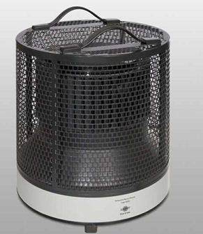
Exemple de source sonore de référence utilisée au LNE
Example of a reference sound source used as a transfer standard at the LNE.

Primary standard sound source

The objective of this part was to produce a primary standard for the acoustic watt in air. This is based on a baffled vibrating solid body (piston). The sound power of this device can be determined from the vibration speed of the body's surface, measured by laser interferometry, and several other variables such as static pressure and temperature. The various candidates for primary sources are based on two techniques: an electrodynamic pot or a loudspeaker ‘motor’. The electrodynamic pot is a vibration source commonly used in laboratories. It drives the movement of a metal piston. The latter must have as much overall movement as possible and as little parasitic movement as possible, due to its lack of rigidity and its natural modes/frequencies at high frequencies. The other method involves using a loudspeaker ‘motor’ that drives a lighter piston. Guiding the piston in a unidirectional and free movement is difficult to achieve. In this project, primary sources were developed by PTB, SP, INRiM and TUBITAK UME.

Diffusion of the ‘acoustic watt’ unit

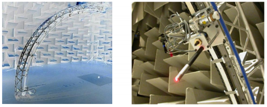
The objective of this part was to develop a system for disseminating the acoustic watt unit using appropriate transfer standards. This made it possible to examine whether existing aerodynamic reference sound sources could be used as transfer standards. The answer was positive, provided that their sensitivity to atmospheric conditions was known. The uncertainty of the sound power emitted by the transfer standards was determined. The objective was for this uncertainty to be only slightly greater than the uncertainty of the primary standard. The LNE developed a scanning apparatus for automated measurement of acoustic power by measuring the acoustic pressure on a 2 m radius hemisphere centred on a reference source flush with the ground.

At LNE, unlike other partners, a single microphone is used, moved to each position by an automatic device and controlled by software that manages both the scanning device and the acoustic signal analyser acquisition. The first movement is made along a rail describing a 90° vertical arc. The second movement consists of moving this arc around a vertical axis to cover the entire hemispherical surface. A third movement moves the microphone along a 1 cm radius to evaluate the intensity in two stages.
Image
"Scanning apparatus" du LNE : vue d'ensemble et détail de la tête de mesure
LNE scanning apparatus: overview (left) and detail of the measuring head (right)

Project website:

http://www.ptb.de/emrp/sib56-home.html

PUBLICATIONS AND COMMUNICATIONS

BREZAS S., CELLARD P., ANDERSSON H., GUGLIELMONE C. and KIRBAS C., “Dissemination of the unit Watt in airborne sound: aerodynamic reference sound sources as transfer standards”, INTER-NOISE 2016, Hamburg, Germany, 21-24 August 2016.

CELLARD P., ANDERSSON H., BREZAS S. and WITTSTOCK S., “Automatic sound field sampling mechanisms to disseminate the unit watt in airborne sound”, INTER-NOISE 2016, Hamburg, Germany, 21-24 August 2016.

Partners

The work was carried out as part of the European project JRP SIB56, which included the following national metrology laboratories:

  • PTB (DE),
  • INRIM (IT),
  • LNE (FR),
  • SP (SE),
  • TUBITAK (TK).

Abstract

Some national laboratories of metrology carry out the continuous expansion method to ensure measurements traceability for low absolute pressure. This method implies to generate a reference molar gas flow rate ranging from 4 × 10-12 mol·s-1 to 4 × 10⁻⁷ mol·s-1. To improve calibrations uncertainties for pressures below 10-3 Pa, Laboratoire national de métrologie et d’essais (LNE) had to initially design a primary reference for gas flow measurement in the aforementioned range, with an expected expanded uncertainty better than 1%. With the gas flowmeter, it will also be possible to calibrate reference leaks, which is an usual activity of the pressure department of the LNE, for the leaks with reference to vacuum between 4 × 10-12 mol·s-1 and 4 × 10⁻⁷mol·s-1 (from 1×10⁻⁸ Pa·m3·s-1 to 1×10⁻³ Pa·m3·s-1) and leaks of the cooling agent R-134a with reference to atmospheric pressure between 3×10⁻⁹ mol·s-1 and 2 × 10⁻⁸ mol·s-1 (from 10 g per year to 60 g·per year). The calibration results of a capillary leak are compared with the pressure rise calibration method, usually performed for this kind of instrument. An uncertainty budget on the gas flow measurement is established for this calibration and applied to the continuous expansion method.

Key words

constant pressure flowmeter
gas flow rate
continuous expansion method
low absolute pressure
reference leak

Abstract

Within the research project “surface activity analysis”, stretching over different metrological and technological topics, mass and nanotechnology for instance, improvements and adaptation have been carried out on different surface analysis devices in laboratories. The goal of this paper is to propose a review of the different developed devices, describing their main improvements for the past four years and to present the experimental results they produced.

Key words

mass metrology
nanodimentional metrology
surface characterization
sorption phenomena
roughness

Abstract

The kilogram is still defined in terms of an artefact, namely, the same prototype sanctioned by the 1st CGPM in 1889. It has three main limitations: available in one place, not really invariant in terms of physical mass and not universal as based on an artefact. The definition of the mass unit could be revised as early as 2011 by basing it on exactly fixed value of a fundamental constant of nature. Thus, the possibility of redefining the kilogram in function of a true natural invariant has been discussed for about 30 years. In this context, the French metrology decided in 2002 to undertake the realisation of a watt balance experiment aiming at linking the kilogram to the Planck constant. The adoption of a new definition of the kilogram based on an atomic or a fundamental physical constant has to take its dissemination into account by avoiding great change for the accredited institutes and most of users. Of course, this will have consequences for the transfer mass standards used by the National Institutes of Metrology.

Key words

references and standards
units of measurement
kilogram
watt balance
silicon single crystal
planck constant
avogadro constant
dissémination

Abstract

The design of a watt balance experiment requires skills in several scientific fields and needs to carry out numerous studies about every element of this experiment. That can be illustrated by the experimental study presented in this article. In order to have a single point of application of a weight and an electromagnetic force balancing this weight, a system of double gimbals with flexure pivots was made out of copper-beryllium alloy. It allows the articulation of the suspensions of the mass and coil generating the electromagnetic force round four coplanar axes which intersect in one point (virtual centre of rotation). The static characteristics of these elastic pivots have been studied in terms of stiffness and elasticity limit. In addition, the study of the dynamic behaviour under vacuum of this device has been carried out in terms of resonance frequency, damping due to internal frictions and coupling between the two systems of gimbals.

Key words

flexure pivot
stiffness
gimbals
watt balance
copper-beryllium alloy

Abstract

Air velocity is a quantity often used in specifications of industrial processes or buildings. In these applications, the velocity is generally below 1 m·s-1, the air temperature can be different from ambient one and the air can flow in any direction whatever. Furthermore, to reach minimum uncertainty measurements, a minimum calibration uncertainty of the used anemometer is needed as well as a calibration as close as possible to measurements conditions. To answer these needs, CETIAT has built a new anemometer calibration test rig. Its evaluation is presented in terms of stability, homogeneity on humidity, temperature and velocity fields as well as calibration uncertainty.

Key words

anemometer
low air velocity
wind-tunnel
calibration
uncertainty
laser doppler velocimetry

Abstract

The smallest mass standard sold until now had a nominal value of one milligram. In order to address emerging needs, the joint LNECNAM metrology laboratory decided to produce and calibrate micromass standards with nominal values down to 100 µg. These standards were developed, then tested through multiple comparisons. They have since been qualified and calibrated through a weighing design, repeatedly and over an extended period of time, so as to establish their stability with respect to oxidation and harmlessness of the handling and storage procedures associated with their use. After five successive calibrations no significant drift was found. Finally, in order to enhance this development, the laboratory obtained an extension of its accreditation to perform mass calibration allowing the extension of the lower limit of the scope of accreditation from 1 mg down to 100 µg.

Key words

microweight
micro-mass standard
submilligram
sensitivity error of mass comparators

Abstract

The national accelerometry references in France are provided by the LNE. Such traceability to national standards is essential for industrial organisations using processes in which an understanding of acceleration related parameters is of primary importance in terms of quality and safety. These fields include the armaments, nuclear, aerospace and automotive industries. The calibration of reference accelerometers for industries and other laboratories has been carried out on the LNE site at Trappes since 2006, using an absolute method involving a Michelson laser interferometer in accordance with standard ISO 16063. The bench used, which is described in “Transfert of the french accelerometry reference from CEA/Cesta to LNE” (RFM n° 10, 2007) is however of an old design and an upgrading program has been drawn up and carried out. This article describes the upgrade of this bench and the improvements. The characteristics of the components of the bench are described. These are the laser interferometer, the shaker and the acquisition and analysis system. In order to cover requirements for traceability chains for vibration frequencies below 10 Hz, a specific shaker for low frequencies has been sourced. Metrological approval was based on the consistency achieved between the calibration results for given accelerometers obtained using the new bench and those obtained using the original bench and on the interlaboratory comparisons.

Key words

accelerometer
vibration
calibration

Abstract

The “watt balance” project aims at linking the kilogram definition to the Planck constant. The weighing of the mass involved requires a determination of the acceleration g with an uncertainty better than 10-8. This work aims at determining g with an atomic gravimeter and a dedicated gravimetric site.

Key words

gravimetry
gravity mapping
gravity model
atomic interferometry
watt balance

Abstract

The continuous expansion method is applied to reference standards of absolute pressure with the aim of improving traceability and reducing uncertainty in the range 1 × 10⁻⁶ Pa to 1 × 10⁻³ Pa. It is a realistic goal to reduce the relative uncertainty by a factor of two down to 2.5% (k = 2). This article describes a study of the method carried out at LNE-LCM. It includes a detailed uncertainty budget.

Key words

vacuum
metrology
continuous expansion
fluxmètre gazeux à pression constante
constant pressure flowmeter